I'm going to talk about a little board I bought for Christmas, called the TinyFPGA BX.
It's something probably of interest to a lot of Raspberry Pi people, though it is quite different and complementary - which you'll hear about in this talk.
It's a board with an FPGA - a Field Programmable Gate Array - and some support components on it - for about 30 pounds.
FPGAs have been around for a long time (1980s), but I've always found it a bit daunting to get started - mostly beause the software stack has looked awkward to use.
Field Programmable Gate Array
First I'll talk about what an FPGA is - a field programmable gate array.
I'll go through what those words actually mean too.
So one way that you can do stuff with digital electronics is have some kind of CPU and run programs on that CPU.
That might be you writing some python on a raspberry pi, that might be you downloading an app onto your phone that someone else has written, or it might be you running C code on an Arduino.
For example, I have a temperature logger running on a Pi, I track my bike rides with a GPS feeding into an app on my phone, and I have some flashing LED goggles driven by an Arduino.
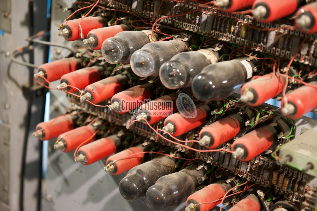
CryptoMuseum /
SparkFun /
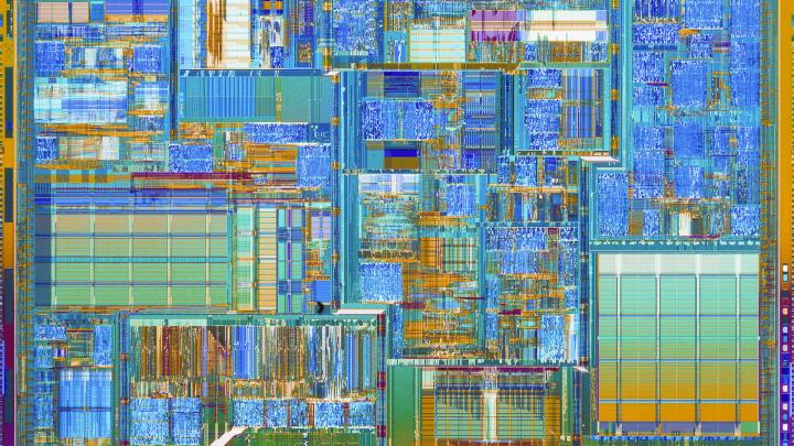
Intel
Another way you can do things with digital electronics is putting together components such as logic gates. That's how you built most of a computer in the first place.
So historically, when they built early computers, they combined valves together to make logic gates. More recently, transisters were invented and used for the same purpose. More recently (around the 1960s)
they invented Integrated Circuits, which are a bunch of transisters on a single chip. Those are the square black lumps you see. CPUs like those used on a Raspberry Pi might have between several million and
several billion transistors on them.
By inductiveload - Own work , Public Domain, Link
Here's a simple common logic circuit: a half adder.
[slide]
It adds two binary digits (which can be written as 0/1, or true/false, or 0v/3v)
and outputs a two digit binary number - the sum of the inputs
A B => A AND B A XOR B 0 0 0 0 0 1 0 1 1 0 0 1 1 1 1 0
We can draw out truth tables for the gates, and for the adder as a whole. These describe, if I put these inputs in, what the output of the gate or the circuit will be.
[slide, augmented, and gesturing]
You can make this stuff more complicated by far, and end up with complicated circuits like CPUs or GPUs, for example.
So an FPGA is a chip with a big pool of logic gates on them, but not wired together in a specific
fixed way: you load the wiring (which sounds kinda magical) as if it was software. If you load in
the design for a CPU, then your FPGA is now CPU. If you load in the design for a different
ciruit, then your FPGA is now that different circuit.
Practical uses
Mobile phones (target of this FPGA)
Specialised compute hardware - in the cloud
LHC triggers at CERN
What are the practical uses of this?
A mobile phone might have an FPGA in it, and a system software update can change how that FPGA is wired up.
On Amazon Web Services, you can do cloud computing with FPGAs attached, and you might upload your own custom designs to handle your specific computations: in the same way that GPUs exist originally for doing specialist graphics computation, and bitcoin miners have custom bitcoin mining hardware, it might be that what you are computing can benefit from having some custom logic rather than being implemented in software.
At CERN, FPGAs are used to filter detector output before it goes into CPU based processing, in the Large Hadron Collider.
Field (my couch) Programmable Gate (AND, OR, NOT, XOR, etc...) Array (lots ofg gates in regular layout)
So that's an FPGA:
Field programmable - i can program it in the field (which for me means on my couch), rather than it being manufactured in a particular configuration
Gate - meaning logic gates
Array - lots of logic gates
https://www.crowdsupply.com/tinyfpga/tinyfpga-bx
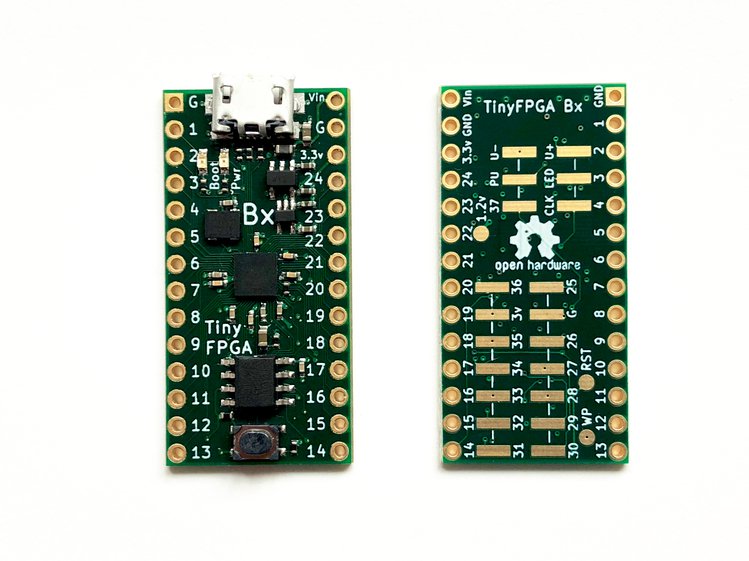
So back to the TinyFPGA BX.
Here's the board
one of these thing black lumps is the actual FPGA chip and the rest is support electronics.
There's a USB port for programming it. If you've used an Arduino with a USB bootloader, it feels very much like that to program.
There are a bunch of IO pins - aside from power, all the other pins are IO pins. These are pretty much the same as the GPIO pins on a Pi or an Arduino. There are more on the bottom as well that are more awkward to access.
Theres also some flash memory.
and a 16 MHz clock.
and a couple of LEDs - one is user controllable.
The software bundle for the tinyfpga comes with two example circuits.
The first one is a pretty classic "flash the LED on the board". I'll go through the code for this a bit more in a minute.
The second example is an entire small computer: an actual CPU and some support peripherals.
You can compile C programs to run on this CPU, and there's a supplied example... which also flashes the LED on the board.
(So from the outside you can't really tell the difference)
Flash an LED - Verilog
input CLK,    // 16MHz clock
output LED   // User/boot LED next to power LED

reg [23:0] blink_counter;

always @(posedge CLK)
    blink_counter <= blink_counter + 1;

assign LED = blink_counter[23];
Let's have a look at some of the source code for the simple LED flasher.
There are languages call Hardware Description Languages, which are for logic circuits what programming languages are for computers. Like programming languages, there are lots of different ones.
The one used here is called Verilog.
I'm not going to give a verilog tutorial, but I'll just point out some interesting things here:
We can define inputs and outputs: there's a 16MHz clock on the tinyfpga board which feeds into a pin on the FPGA, and there's an LED controlled by the FPGA.
We can say to create a register on the FPGA: basically a simple piece of memory - this one is 27 bits long. everything is in bits not bytes, because all the logic is bitwise. there's not a particularly natural "byte" size inside the FPGA.
and we can say "wire in the right kind of gates so that every time the clock ticks, that register is incremented by one".
So you don't have to explicitly say "I want an AND gate and an XOR gate and whatever": the language is high level enough to know that when I say + that I mean to declare (in this case) a 27 bit adder, and to put in the wiring to connect it to the register appropriately. - this style is called "Register Transfer Level"
the last interesting bit is we just say to directly wire bit 23 of the counter register up to the LED output port:
So a lot of this kinda looks like writing a computer program - but the point is that it gets turned into connections of logic gates on the board.
CPUs
Retrocomputing: BBC Micro (1980s)PDP/11 (1970s)
Modern CPUs: picorv32 - RISC V
What sort of projects are interesting? What's a low end FPGA good for that say a £1 microcontroller or a £5 pi zero isn't good for?
One thing seems to be CPU projects: the retrocomputing crowd is quite interested in replicating
systems from the past on FPGAs, and some people build new CPUs - for example, one of the examples
that comes with this board is a RISC V cpu and peripherals.
Because the risc-v instruction set is standardised, you can use a regular C compiler like `gcc` to compile code that targets this instruction set - and so fairly straightforwardly compile code to run on this CPU.
Timing sensitive protocols
Another thing that you can use these for is very timing sensitive protocols: that's something
Raspberry Pi has had difficulty with - originally you couldn't drive NeoPixels from it, although
more recently you can use some specialised functionality, not the CPU, to get the right
signals out - that specialised functionality on the Pi you could also implement in an FPGA.
Or perhaps interfacing to particular buses - my 1980s computing interest means I'm quite interested
in doing something with the BBC Tube coprocessor interface, as a bridge between a Pi and the
BBC.
Because every different definition in verilog is implemented as its own bit of hardware in the FPGA, everything runs in parallel, not serial like on a CPU - what happens in one place won't affect the timings of another place so much.
Vocabulary
bits
byte = 8 bits
Hardware description language (HDL)
programming language
Intellectual property core (IP core)
library
register
variable
synthesis / place-and-route
compiling / linking
bitstream
compiled code
The vocabulary (and culture) of hardware design is a bit different if you're used to programmer
terminology. Here is a random selection of rough translations.
Demo 1
Live demo:
Start with tinyfpga programmed to do not much (eg. all LEDs off).
When you power it up, it goes into bootloader mode, waiting for something to be downloaded.
So lets go over to this terminal window and make something we can download.
Compile verilog program and tinyprog it into the fpga and hold it up showing it working - flashing all 4 LEDs once per second - clear to see whats happening there.
$ apio build
This gives us hardware.bin (ls -l)
which is the bitstream to download into the FPGA.
Then tinyprog -p hardware.bin
and see the LEDs flash
Demo 2
- then i'll download a more interesting one that lets you fiddle with the colours (without showing the code, just run tinyprog in a different directory)
(and that's how I'll leave it for people to play with - and this is the last talk so we can play right away/in pub)
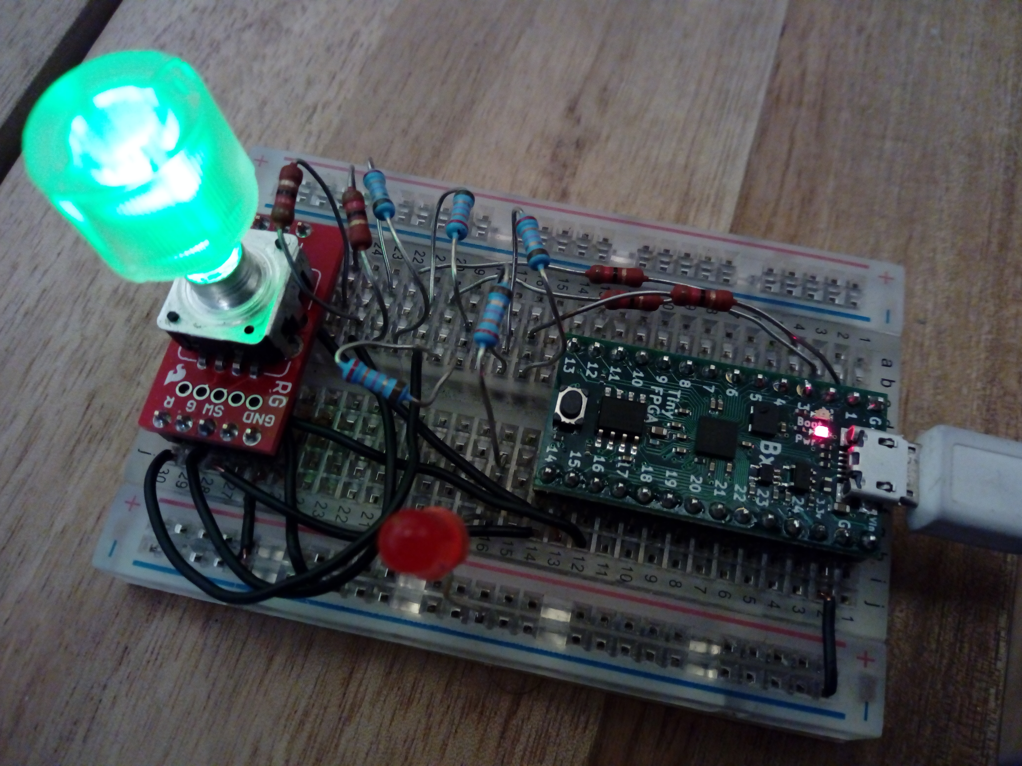
So as it comes, the board doesn't have pins on it. I've soldered pins on and stuck it onto breadboard, along with a few other components.
I've wired up another LED and a rotary encoder so I can do more interesting input and output stuff - there are some notes on that on the web page for this
talk.
you can rotate to change colour and press the button to make it flash.
Mention: rotary encoder decoder, counter for colours, PWM generator for pulsing, setting the input pis into a specific mode (turn on pullups)